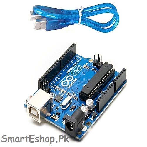

- Arduino relay modules how to#
- Arduino relay modules code#
- Arduino relay modules download#
- Arduino relay modules free#
You can always add more sensors to the device, upgrading it to a much-sophisticated device.Ĭlick the button below to download the source code. This device is simple to create and can be used in other projects as well. So there you have it – a Relay Module Connection in Arduino. Successful upload will result to a the lamp turning on and off again for 3 seconds.
Arduino relay modules code#
After that, upload the code to the Arduino. int RelayPin = 6 Ĭonnect your lamp to a wall socket, Double-check the wiring. In the loop function, digitalWrite function is used to turn on or off the relay module. Then for the setup, simply set the pin mode of the declared variable to OUTPUT. HIGH POWERED ELECTRICITY IS INVOLVED.įor the code, first is to declare the data pin of the module. To connect the 4 Relay board to an Arduino is very easy and allows you to turn on and off an wide range of devices, both AC and DC. Relay Module Wiring DiagramĪGAIN, PLEASE BE CAREFUL IN WIRING. Signal pin of the relay is connected to the digital pin 6 of the Arduino. The relay itself is powered using the 5V power of the Arduino. The red wire of the lamp is connected to the COM terminal and to NO terminal of the relay. Screwdriver (to connect wires to the relay module) x 1 DC motor (load) x 1 Software. Arduino Uno Rev3 x 1 Relay Module x 1 Dupont wire x 3 Arduino USB cable (for powering and programming) x 1 Batteries (or DC power supply) Battery connector Tools. You can connect here if you want your relay to be open by default. 1: Components Needed To Control Relay Using Arduino Hardware Components. This is the opposite of the other terminal. IoT Course will help you out to build such a Customized IoT Solutions. A Relay is actually a switch that is electrically conducted by an electromagnet. On the other hand, the top terminal is the Normally Open terminal. Step 1: About This Project We can easily control high voltage electronic devices using relays. This terminal is used if you want to turn off your relay by default. The bottom terminal is the Normally Closed terminal. This is where you connect signal you want to switch (example: electricity). The output terminals are COM, NO, and NC. This module has 3 pins – Signal, Power, and Ground. It can switch up to 10 amperes with 250 volts of AC or 30 volts of DC. The single relay module below is rated to switch a single high-powered device from the Arduino. You can use 2-channel or 3-channel, it simply depends on the project requirements. This project uses a single channel relay module. This is great for all kinds of IoT projects.

Arduino Uno is suitable for any projects and is the cheapest and widely used microprocessor board in the Arduino family. To start this project, you need the following: Qty Component 1 Arduino UNO 1 Single Channel Relay Module 1 LED bulbįor this project, we will be using an Arduino Uno microprocessor board. Also connected the ends of the cable to the plug and the socket.Įxample of a demonstration of Lamp using the relay module as shown in the image.Arduino Remote Control Light Switch with Code and Wiring Diagram | Arduino Projects with Source Code So with this configuration when we will initiate the relay we will get the high voltage circuit closed and working. One of the two wires will be cut and attached to the common and the normally open pin of the module output connector.

Shop No.1A, Ground floor, Al Khalil Center, 16 Hall road Lahore. Office No.6,7,8, 1st floor, Rehman Electronics Center, 22 Yasin street, Hall road Lahore. Now for the HIGH Voltage part, we need a power plug, a socket and a cable with two wires. Transparent Case Acrylic Casing for 1 Channel of Timer Relay Module. The Arduino’s 5V pin will be attached to the Vcc pin of the module and the pin number 7 to the In1 input pin for managing the relay. As previously defined we will use a 5V Adapter as a separate power supply for the electromagnet connected to the JDVcc and the Ground pin.
Arduino relay modules how to#
How to use relay module with the High Voltage Devices : Let’s take a look at the circuit diagram. Inside of it, there are electromagnets with a contact that closes the circuit when you apply voltage to it. The electromagnet is initiated with a low voltage, for example, 5 volts from a microcontroller and it extracts a contact to make or break a high voltage circuit. You can choose the one that best meets your needs. Modules with two, four, and eight channels are also available. It has a relay with a maximum current rating of 10A at 250VAC or 30VDC.

The one-channel relay module is designed to allow your Arduino to control a single high-powered device. IoT Course will help you out to build such a Customized IoT Solutions. One-Channel Relay Module Hardware Overview.
Arduino relay modules free#
This article is a compilation of 25 free guides for ESP32 sensors and modules. We have tutorials for the most popular components. A Relay is actually a switch that is electrically conducted by an electromagnet. There is a wide variety of sensors, modules, and peripherals compatible with the ESP32 boards. We can easily control high voltage electronic devices using relays.


 0 kommentar(er)
